If for some reason you and a friend ever wondered who was better at flexing a flex sensor just right you can now settle it with Flex-it. Flex-it is a my second original project working with the SparkFun RedBoard.
Flex-It is a small game in which two players each has a flex sensor which corresponds to each players’ own LED, either red or blue. The LEDs begin light and as you flex the sensor you either make the LED brighter or dimmer. The object of the game is to dim your light below a certain point. Whoever succeeds at this first wins the game and locks the sensors and LEDS. To make sure the players know who has won the RGB LED will light up with the appropriate winning color, i.e. if the blue player wins the RGB LED will light up blue and if the red player wins it will light up red. After that if you push the button the RGB LED will flash green and the game will reset. If the players want to keep track of their score they can open up the Serial display for this. However, make sure to open it before you begin playing, because it will reset if you open it up after a few rounds and you will not have records of who won those.
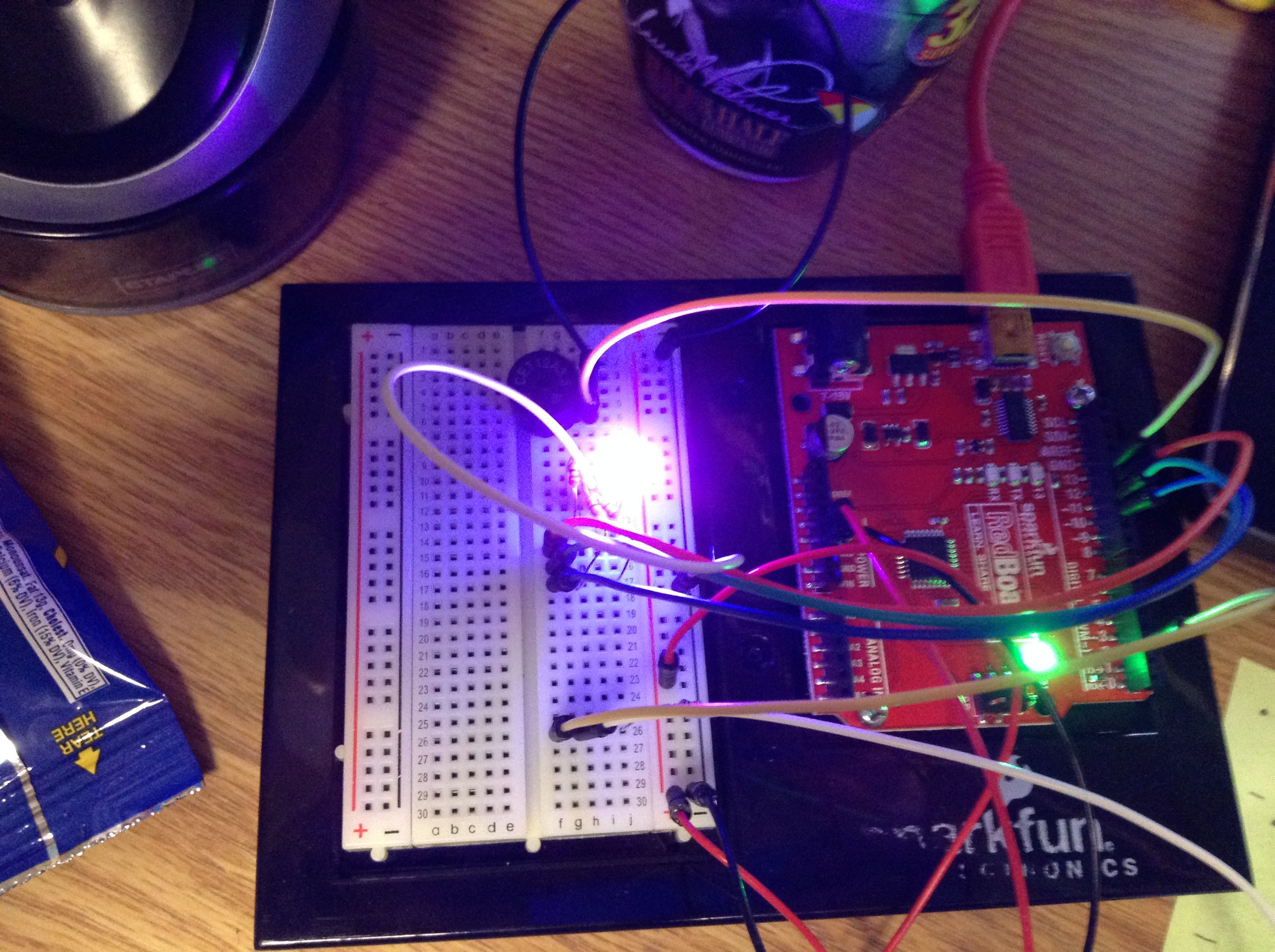
(My apologizes about the difficulty to read the computer screen. It simply displays the score after each light has been lit up.)
The assignment called for us to use analog inputs and outputs. After playing around with a flex sensor in class for a while and using it with a motor, I found the device was rather interesting to use and figured I should explore it more. After some thought I decided I liked the idea of having two players compete to turn off LEDs. I started sketching this idea and then decided I should add the RGB LED so that it was more clear who was the winner. Shortly after I decided that it would be good idea to add a button to the set up so that it would be easy to reset the game. This idea appeared even better when I began coding and found that originally I would have to reset the whole Redboard to get the game up and running and that was more of a hassle than it should be.
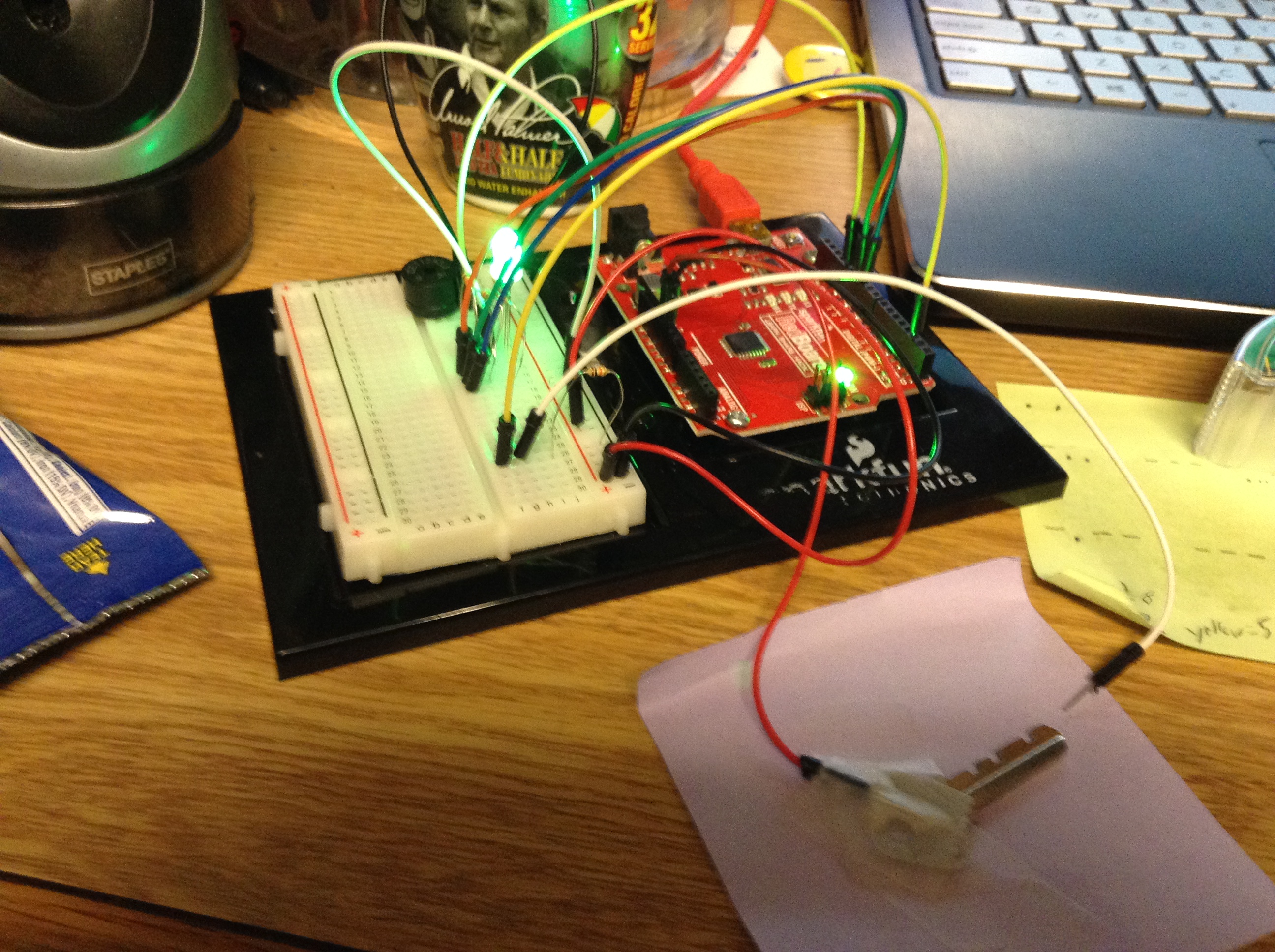
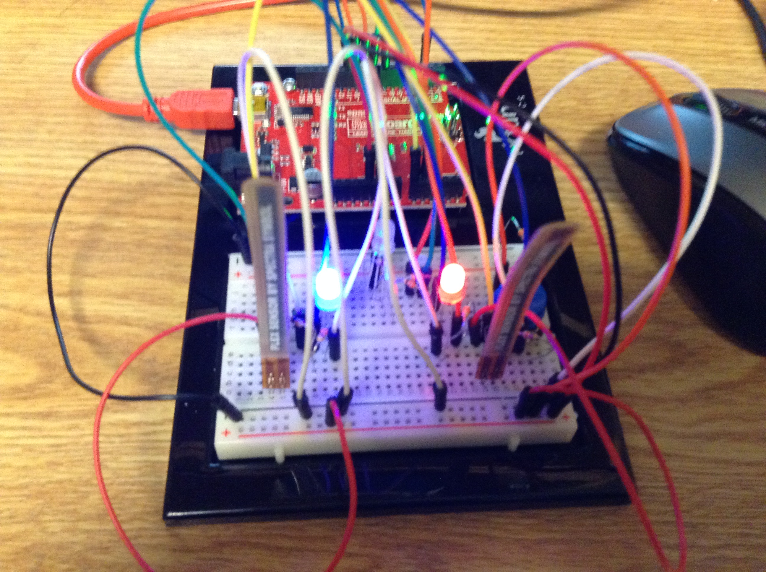
Some of my biggest challenges came with the wiring, I made a few dumb mistakes hooking up resistors and wires to appropriate parts. For example I accidentally hooked up the push button wrong and had the five volts running in the same row as the wire attached to the pin, thus making it read wrong. I also had some trouble setting up the appropriate range for the flex sensors and LED brightness. This range may be able to be adjusted slightly more accurately with more skilled and practiced hands, but I feel I got it as close as I could. It also took me a while to get the code for the push button worked out. I had to get the help of my instructor to figure out to use the return() function correctly. Finally, I had the idea to keep track of the score and have it be posted to the Serial display using Serial.println();. After that I had the finished product seen below.
If you’d like to build your own Flex-It then read below for schematics, parts, and the code.
Parts:
(1) SparkFun Redboard or Arduino Uno
(1) Blue LED
(1) Red LED
(1) RGB LED
(2) Flex Sensor
(5) 330 Ohm resistor
(3) 10K Ohm resistor
(1) push button
(Approx. 19) Wires
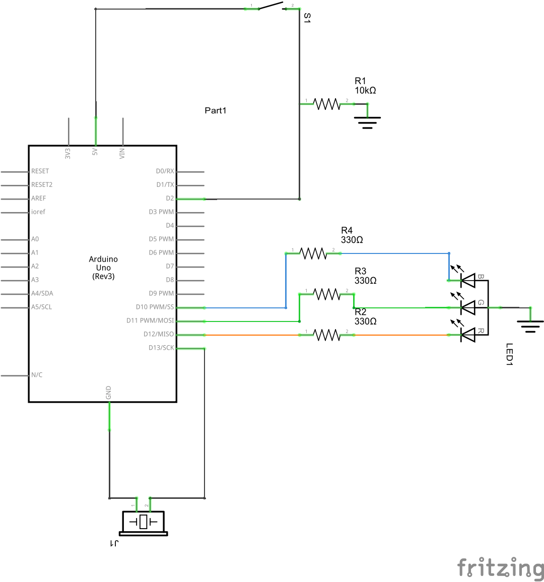
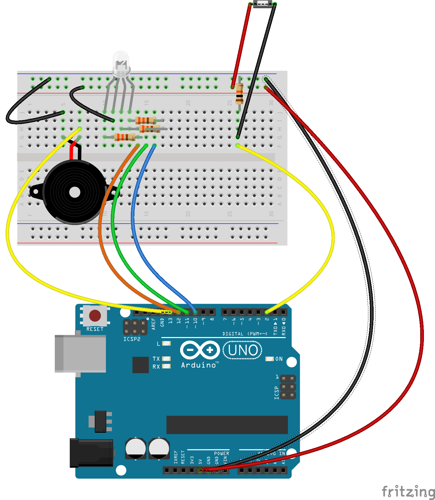
The basic schematic and sketch can be seen below
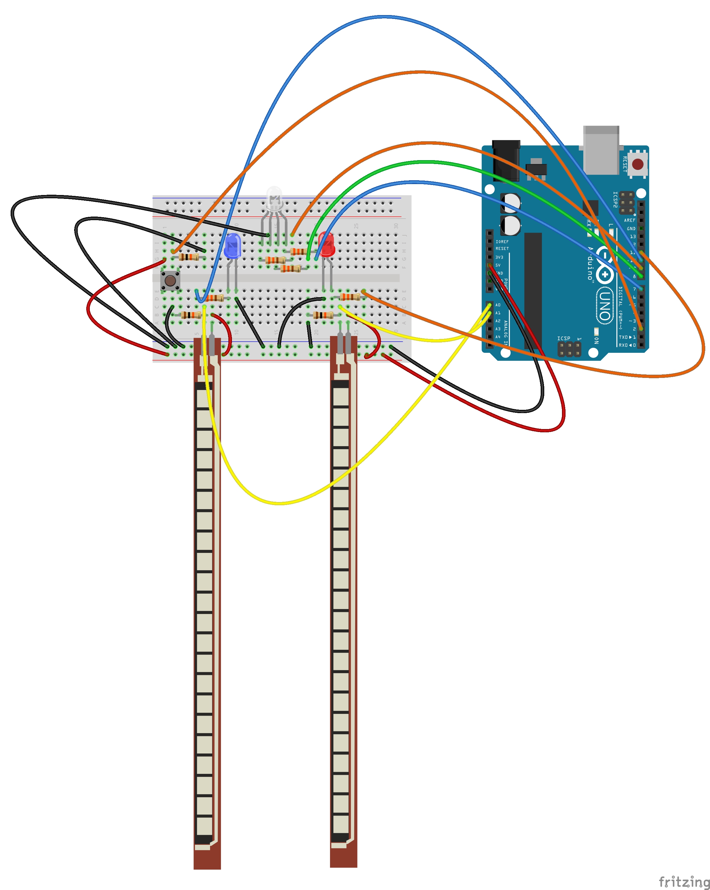
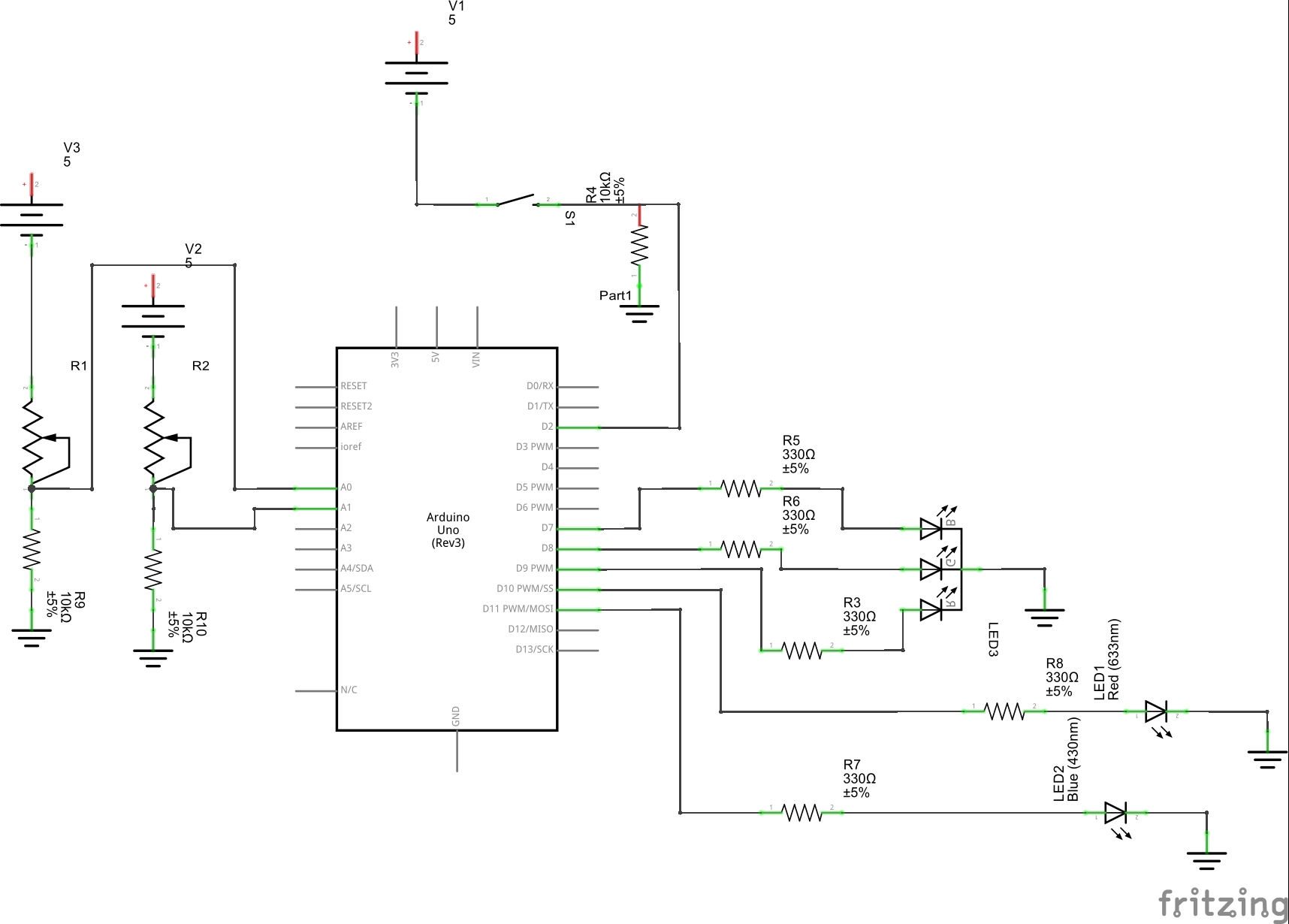
You want to hook up the a wire attached to 5 volts to one end of the flex sensor, it should be to the side that leads to the thin line of the flex sensor. From the other side you want to run a 10K Ohm resistor to ground and then have a wire hooking it up to one of the analog output pins, I used A0 and A1. You want the negative end of the blue and red LEDs and the ground pin of the RGB LED to run to ground. Then run a wire from pin 11 through a resistor and into the positive side of the blue LED. Do the same with the red LED to pin 10. You can use any pin you desire, as long as it has pulse width moderation – marked by a tilde (~) – since we will be using analog output for these LEDs. Then hook up the red, green, and blue pins of the RGB LED to any digital output pin, I used 9, 8, and 7 respectively. Run 5 volts into one row of the button and run wire out of it to a digital pin and through a resistor to ground.
The code I used is listed below, feel free to make any modifications deemed necessary.
/* Flex-it
The game should work that two players flex the sensors
with the intent of dimming the light to a certain point.
Whoever succeeds first the RGB LED will light up that color, i.e.
if blue wins then the RGB LED will light up blue.
If the push button is pressed it should reset the circuit so
it can be played again. And if the Serial screen is opened it will keep
track of the score, though it must be started before the two players begin.
*/
//Set up variables
const int blue = 11;
const int red = 10;
const int RGBred = 9;
const int RGBgreen = 8;
const int RGBblue = 7;
const int pushButton = 2;
const int minRed = 15;
const int maxRed = 330;
const int minBlue = 15;
const int maxBlue = 345;
int counterRed = 0;
int counterBlue = 0;

void setup() {
  // set up our inputs
  pinMode(pushButton, INPUT);
  //set up our outputs
  pinMode(RGBred, OUTPUT);
  pinMode(RGBgreen, OUTPUT);
  pinMode(RGBblue, OUTPUT);

  Serial.begin(9600);
}

void loop() {

  digitalWrite(RGBgreen, LOW);
  int redSensor; // define a variable for the red light's sensor
  int blueSensor; // define a variable for the blue light's sensor
  int redMap; // map the range of the red sensor to fit analog values better
  int blueMap; // map the range of the blue sensor to fit analog values better

  redSensor = analogRead(A1);
  blueSensor = analogRead(A0);


  //have the values of the sensors sent to our computer
  //so that we can set our output to the most appropriate values
  //Serial.println("redsensor:");
  //Serial.println(redSensor);
  //Serial.println("redmapping");
  //Serial.println("bluesensor:");
  //Serial.println(blueSensor);
  //delay(1000);
  //These were used for debugging and are limited to comments
  // so the final score can be displayed with less clutter.

  //constrain the results of our sensor to the sweet
  //spot of the flex senors
  redSensor = constrain(redSensor, minRed, maxRed);
  blueSensor = constrain(blueSensor, minBlue, maxBlue);
  //map the values of the sensor to be more accurate
  //with analogWrite
  redSensor = map(redSensor, minRed, maxRed, 0, 255);
  blueSensor = map(blueSensor, minBlue, maxBlue, 0, 255);

  analogWrite(red, redSensor);
  analogWrite(blue, blueSensor);
  int buttonState; // set up a variable to use for our reset button


  while ((redSensor < minRed)) { //indicates that red won
    digitalWrite(RGBred, HIGH);
    analogWrite(blue, 255);

    buttonState = digitalRead(pushButton); //check the value of the push button
    if (buttonState == HIGH) { //resets the game
      analogWrite(red, 0);
      digitalWrite(RGBred, LOW);
      analogWrite(blue, 0);
      digitalWrite(RGBblue, LOW);
      digitalWrite(RGBgreen, HIGH);
      counterRed++; // keeps track of how many times red has won.
      Serial.println("Red Wins:");
      Serial.println(counterRed);
      Serial.println("Blue Wins:");
      Serial.println(counterBlue);
      delay(1000);
      return (loop());
      Serial.println("it works"); // message to ensure the switch work

    }
  }

  while ((blueSensor < minBlue)) { //indicates that blue won
    digitalWrite(RGBblue, HIGH);
    analogWrite(red, 255);

    buttonState = digitalRead(pushButton); //check the value of the button
    if (buttonState == HIGH) { //resets the game
      analogWrite(red, 0);
      digitalWrite(RGBred, LOW);
      analogWrite(blue, 0);
      digitalWrite(RGBblue, LOW);
      digitalWrite(RGBgreen, HIGH);
      counterBlue++; // keeps track of how many times blue has won.
      Serial.println("Red Wins:");
      Serial.println(counterRed);
      Serial.println("Blue Wins:");
      Serial.println(counterBlue);
      delay(1000);
      return (loop());
      Serial.println("it works"); // message to ensure the switch worked
    }
  }
}
The code is rather simplistic. The comments clarify most of the points, but I will go over the main points here as well. Basically the code starts out setting up our variables and then we tell it to read the input value of the analog pins (we do not need to specify these as inputs at the top since they are analog). We then read these values and found a range to use. We use this value to constrain the values we read and then to map it to a relative range for our analog outputs. The code then continues to check these until either the red or the blue analog out reads as less than the minimum, in which case it will light up the RGB LED and stop calculating the analog values. It also adds one to the appropriate scorer’s points. Then the code checks for the status of the push button and if it reads as high it returns to the beginning of the loop and the code repeats as long as it has power.
The project could be extended to any form of analog input, such as a potentiometer. It would also help to use a larger breadboard to avoid as much clutter. The larger breadboard would also allow for using a LCD display for the score rather than the computer Serial monitor. If I had had room I would have incorporated this, but I thought of it too late to update the size of the breadboard. As I said earlier the values for the maximums and minimums could probably be altered to give more precision as well. Also I occasionally have issues where the flex sensors will come out of their pins while being flexed. This may be a user error, but it would still help if there was a way to get them to stay put better.
Thanks for reading and I hope you enjoyed!