The Accelerometer cart is the second intermediate project I made up. Simply it is a small little robot that receives inputs from a triple-axis acceleroometer and moves in an appropriate direction accordingly.
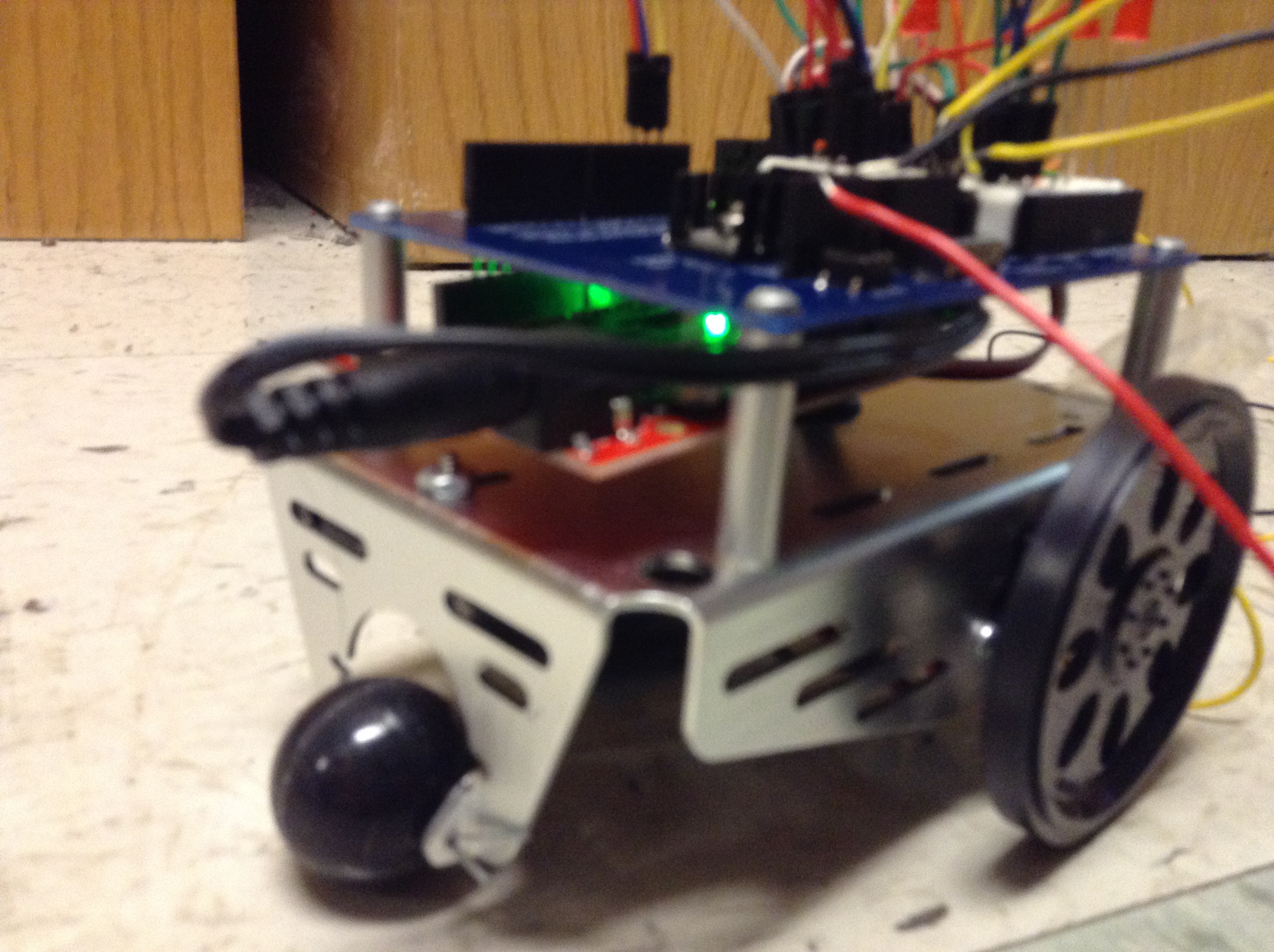
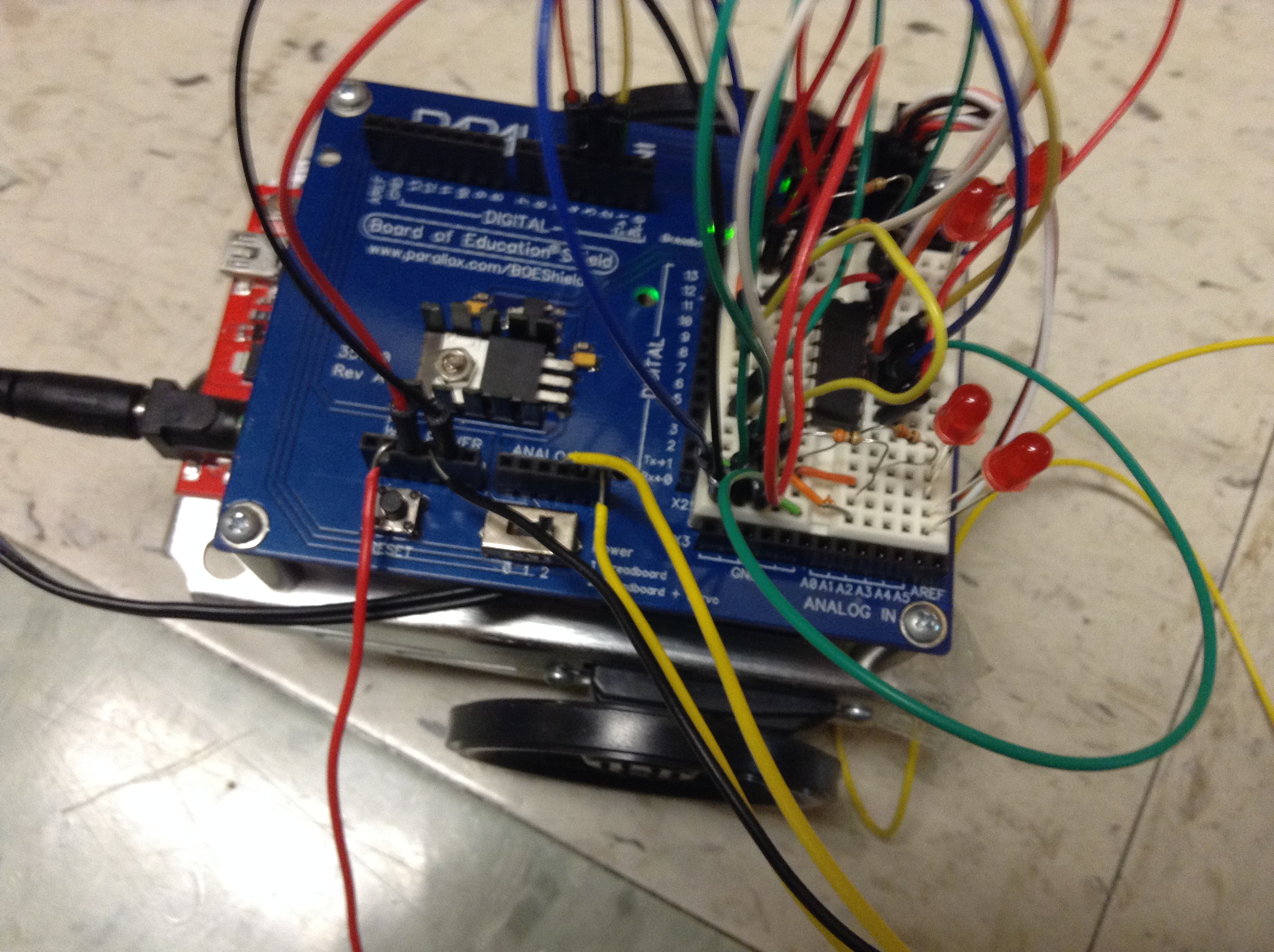
The Accelerometer Cart uses a triple-axis accelerometer to input the direction the device is being tilted. This information is then sent to a SparkFun Redboard which then outputs it to two servo motors which will spin wheels in the appropriate direction and thus move the little robot chassis. The robot chassis was from a Parallax Inc Board of Education Shield that my instructor provided for me. You can find out more about this at this link. Basically it is metal body which has batteries and the servos tucked underneath of it. It then has a wheel attached to each servo and a rolling ball on the front to help give it more support. It then has a shield on top that the Redboard or Arduino can easily fit into. The shield also includes a little bread board to hook up items on the top. It also uses a shift register and LEDs so that when the accelerometer is tilted back towards the person holding it the cart moves backwards and the LEDs light up and that when the accelerometer is tilted to either side the LEDs on that side blink as the cart begins to turn in that direction.
This was the second project that I had to think of what I wanted to do by myself. I did not know what I wanted to do at first, but I liked the idea of using the triple-axis accelerometer to control some sort of motor. I did not know what kind of device to use with this at first, but eventually after thinking I had the idea to use it with some DC motors that had wheels attached to create a little device to drive around depending on how the acelerometer was tilted. I talked with my instructor about this idea and he approved, but we did not know at first how to find wheels that would work with the DC motors without permanently gluing them to the motors. My instructor then remembered that the school had the robot chassis around and after we made sure that no one else in the class wanted to use it he told me I could use it. With that I decided to incorporate the shift register and LEDs into the device to give it a little more. I did not know how to do this at first, but then I decided to use them as a sort of tail lights. With that I had the final design.
I ran into a few difficulties while making the project. One was getting the wires to be long enough to put distance between the accelerometer and the chassis and still have it work appropriately. This also believes to what I believe to be the biggest issue with the device. Occasionally I believe one of the wires connected to the accelerometer or the chassis comes unconnected and whatever wheel is spinning at the time gets stuck spinning. A simple reset will usually solve the issue right away though and if not then making sure the wires connecting the accelerometer will more than likely fix the issue. This could be a bug in the code, but as I said I believe it is due to wires coming loose. It also took me a little time to get the LEDs and shift register to work properly, and the slight delay I put in the blinking with the “turn signal” can sometimes be a hindrance, but this is rare and far between.
If you would like to build your own Accelerometer Cart then keep reading to find parts, schematics, sketches and code below.
Parts:
(1) Arduino Uno/ SparkFun Redboard
(4) Red LEDs (could be any color you want)
(1) 74HC595 shift register
(6) 330 Ohm resistors
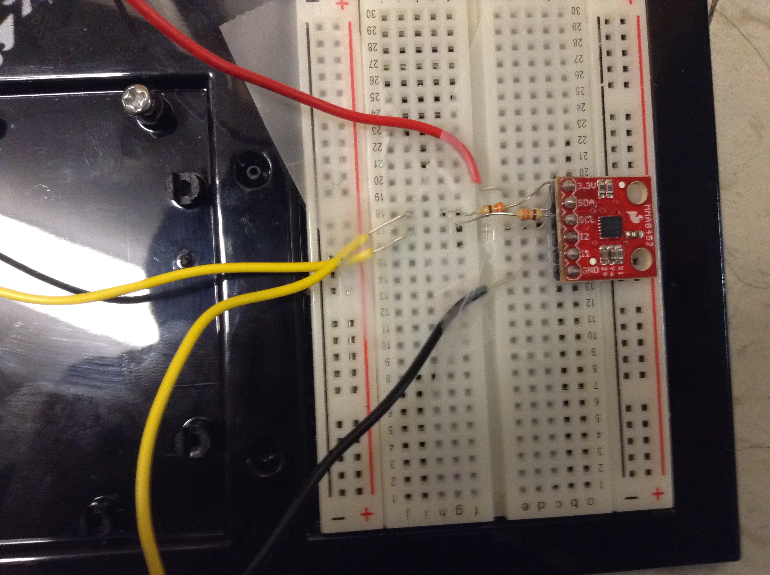
(1) MMA8452Q Triple-Axis Accelerometer
(1) Parallax Inc BOE Robot (If you do not have or do not want to build this you could use servo motors and attach wheels, just make sure they can spin all the way around and that you can properly support it)
Several wires, long ones will come in handy, and almost be necessary.
The basic schematic and sketch can be seen below:
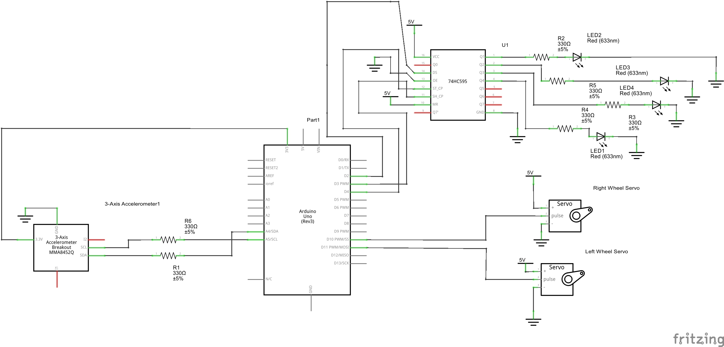
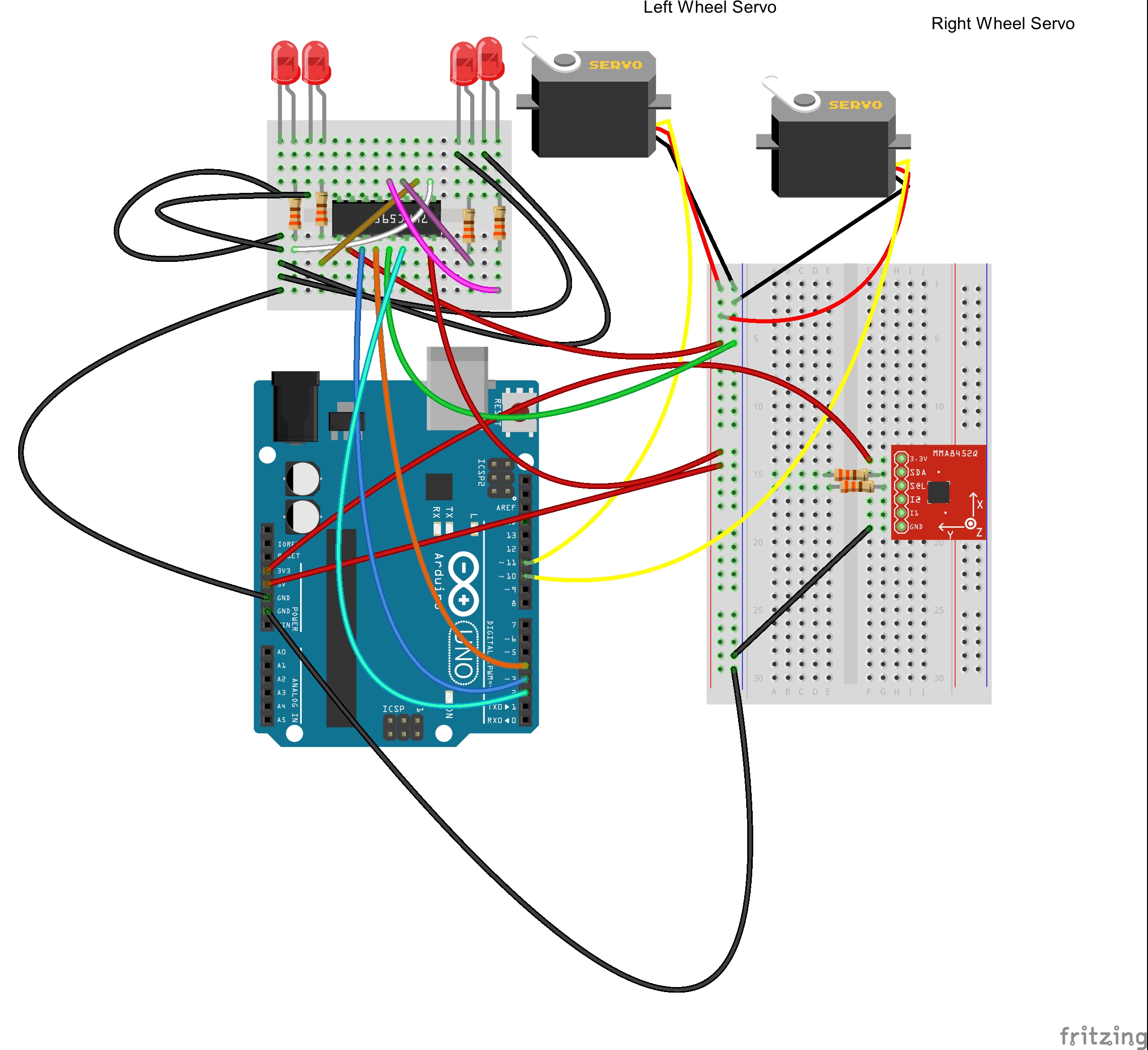
(NOTE: the software I use to design the sketches and schematics, Fritzing, does not have any parts for the Parallax shield that I could find and I do not have the knowledge to design them myself. So I simply set up the sketches and schematics as if they were being hooked up to the servos directly. I put the little breadboard in the sketch to represent the breadboard on the top of the Parallax board and the larger breadboard is where the triple-axis accelerometer is hooked up.)
You want to hook up your triple-axis accelerometer with power running from the 3.3v pin on the Redboard to the 3.3v pin on the accelerometer and run the ground pin of the accelerometer to the ground on the Redboard. Then from the SCL pin on the accelerometer use a resistor and run it to A4 and SDA to A5. A4 and A5 act as substitutes to the SCL and SDA pins which are not present on the Parallax board. On the BOE Bot there are nice little pins in the upper right corner that allow for the easy plugging in of the servos. I plugged the right one into 10 and left into 11. Then to run the shift register you need to run 5 volts into the VCC pin and the SRCLR pin and then run the Ground pin and the OE pin to ground. Then run the SER pin on the shift register to pin 2 on the Redboard, the RCLK pin to pin 4, and the SRCLK pin to pin 3. Then run the Qb, Qc, Qd, and Qe pins through resistors into the LEDs (in that order you would do Qb = far right, Qc = mid right, Qd = mid left, Qe = far left) then into ground. This allows the shift register to only use three Redboard pins to control the four LEDs.
The code is listed below, feel free to use it and edit it as seen fit.
The code is pretty straight forward and the comments should explain any confusing parts. The code basically works by monitoring the state of the accelerometer and then calls the function to print this to the serial monitor and depending on the orientation it moves the wheels and lights up the LEDs. The excerpt below shows the case for when the accelerometer is tilted forward. This first turns off any lights, in case we were moving backward anytime before this. Then it prints the orientation to the serial monitor and then it attaches the two servos to the appropriate pins. It then spins both of the wheels to move the chassis forward. The left wheel moves counterclockwise, which is why the value assigned to it is 170, since with the servo the closer to 180 it is the faster it spins. The right wheel moves clockwise, which is why it has an assigned value of 10, since the closer to 0 it is the faster it will spin in the clockwise direction. The code for each direction is similar to this, expect it plays with the values of how the wheels spin.
[cpp]
case LANDSCAPE_R:
for (index = 1; index <= 4; index++) {
shiftWrite(index, LOW);
}
//this will turn off the LEDs as we move the
//accelerometer back to flat
Serial.print("Landscape Right");
servoRight.attach(10); //this will attach our right servo motor and wheel
// to pin 10
servoLeft.attach(11); // this will attach our left servo motor and wheel to pin 11
servoRight.write(10); //this will make it so that when the accelerometer
// is tilted forward it will move the right wheel clockwise
servoLeft.write(170); //this will make it so that when the accelerometer
// is tilted forward it will move the left wheel counterclockwise so it
// will move the same as the right and the device will move forward
break;
[/cpp]
As I mentioned before the device does sometimes get stuck moving in one direction, most notably when turning. I believe this is an issue of the wires coming loose, so if someone wanted to make it more stable soldering the wires to the accelerometer or at least into a better holder it would probably improve the devices stability. An even better option would to use inferred so the device could be made wireless and again improve the stability issue. The speeds could also be played with to make it a little less touchy, as well.
Thank you for reading! 🙂