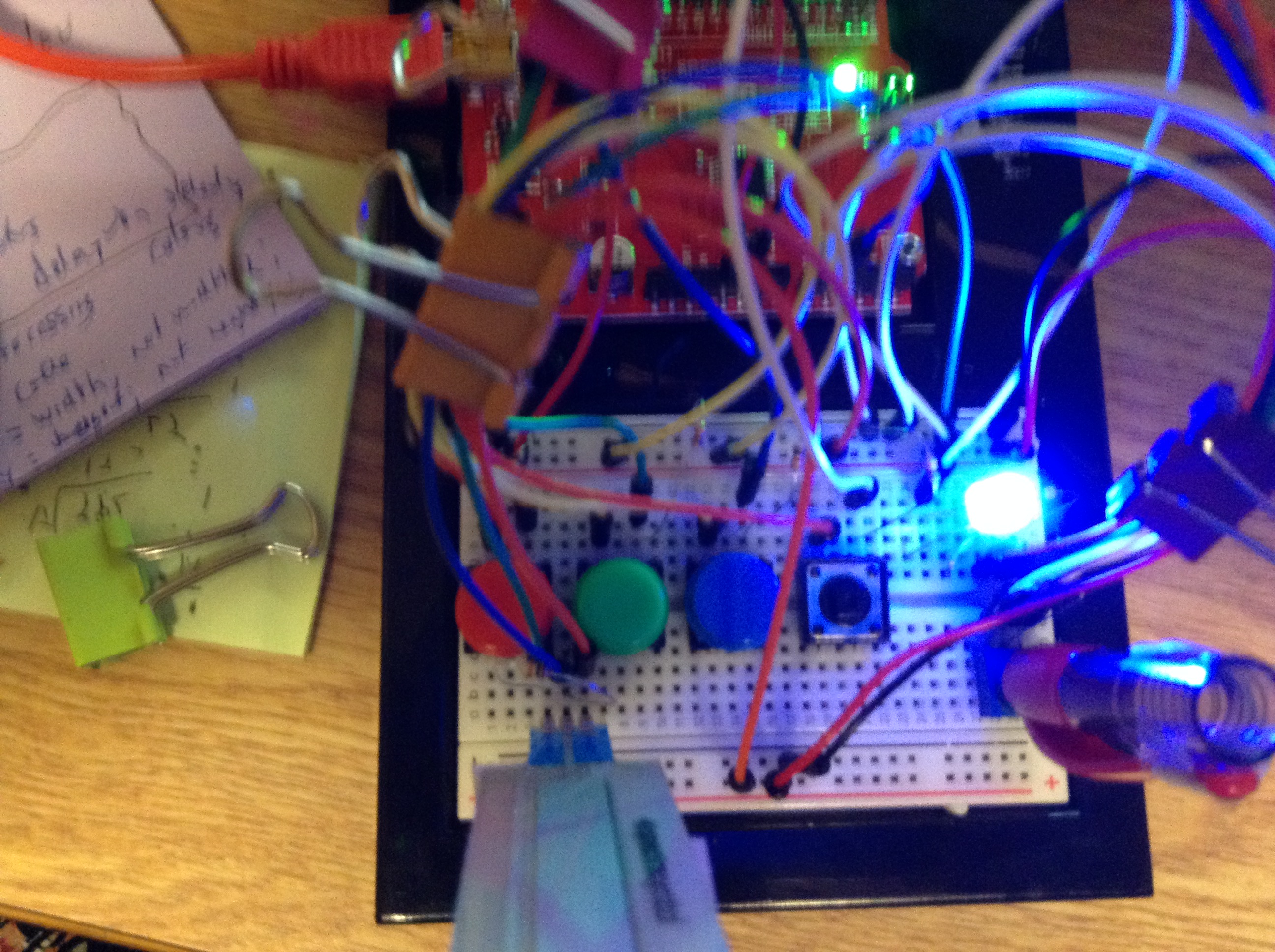
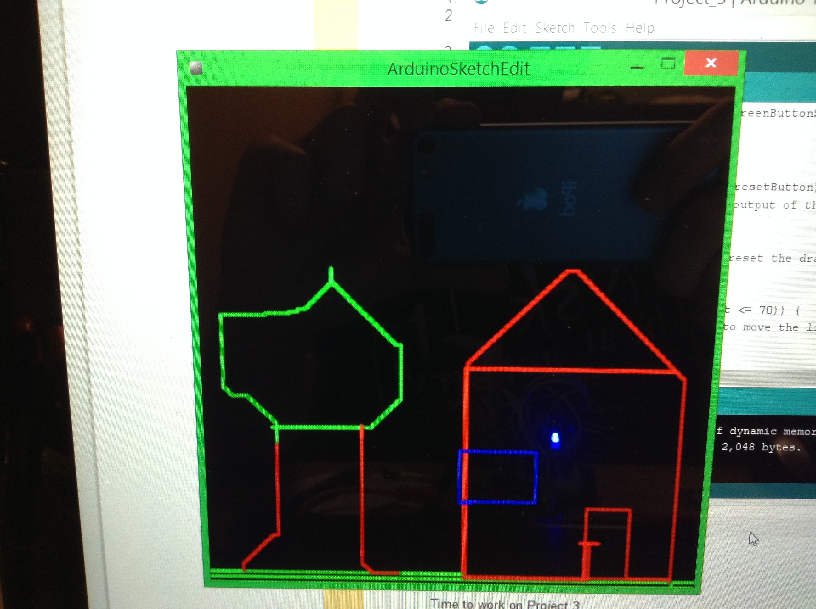
This little project is a simple device I am calling the Arduino Sketcher. The name says the majority, but it is a simple device that using a Processing code and SparkFun Redboard can be used to draw pictures on your computer screen.
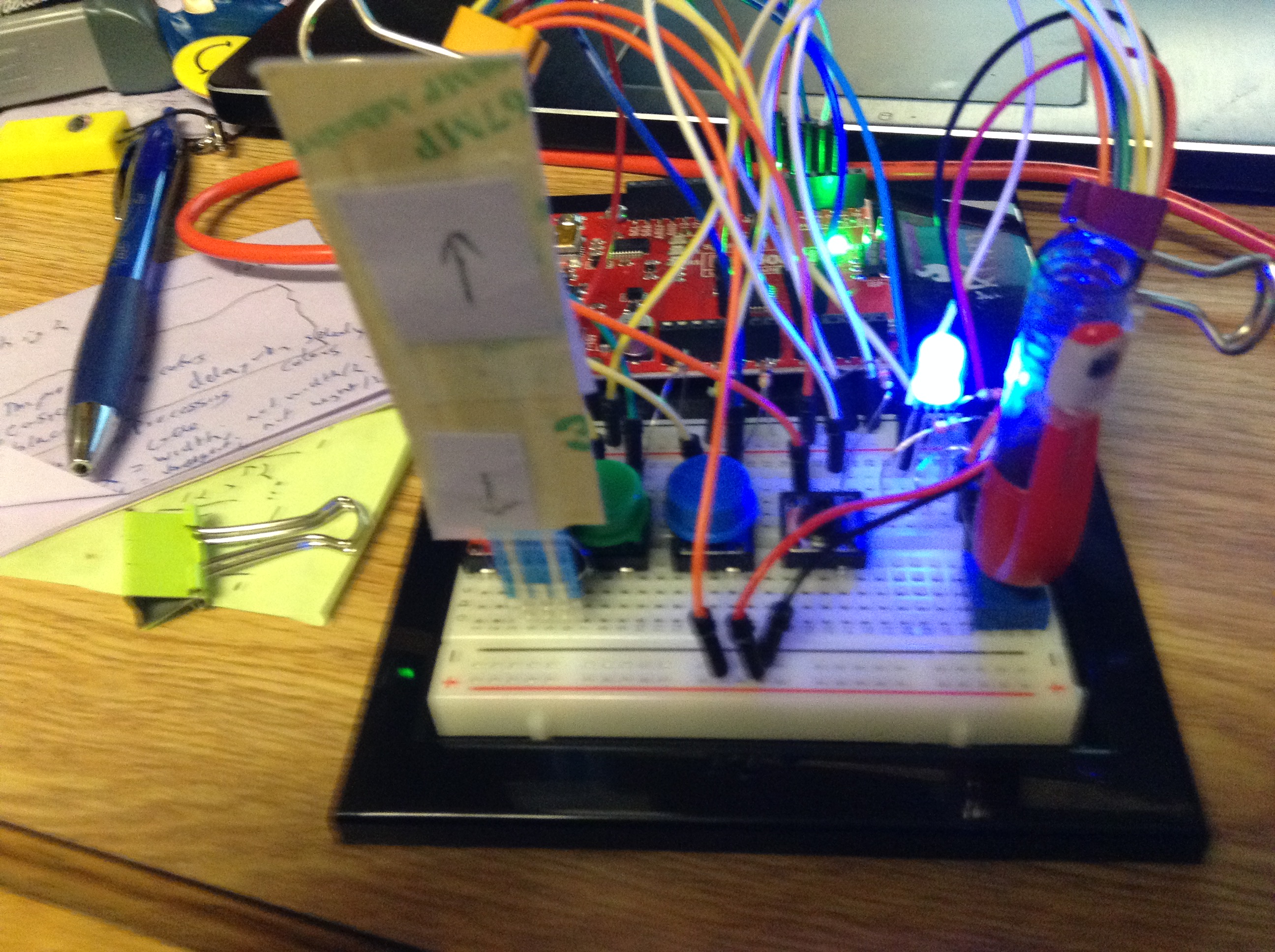
The device is made up of four push buttons, one red, one green, one blue, and one without a color. Each one when pushed will change the color of the lines being draw to the color of the button, and in the case of the one without a color it will reset the drawing. If both the red and blue button are pushed and released at the same time it will make the color magenta, and the same goes for other color combinations. Thought this is very touchy and can be difficult to use. A RGB LED is displayed on the screen to show which color you are currently using. There is a soft potentiometer that when pushed at the top will move the line up, and when pushed down will move the line down. There is also a regular knob potentiometer which when turned to the right moves the drawing line to the right and when to the left moves the line to the left.
The assignment called for us to create an interface to use with this Processing code that our instructor provided to us. This interface needed a way to draw, change the color, and reset the canvas. I thought about it for a while and eventually decided that using the soft potentiometer could be an interesting and good idea to use for the drawing. I originally thought that I would be able to include all four directions on one soft pot, using the different ranges that the different spots on the soft pot provided for each direction. I soon changed this idea, because I thought it would make the soft pot too crowded. I then tried thought I would simply use two of these, but after experimenting with the knob potentiometer I found this was a fairly good interface device, and decided to pair it with the soft pot. I had decided pretty early that using the buttons and the RGB LED to control and display the color being used to draw with.
I ran into a few issues while working on the project. Mainly it took me a while to figure out the code for how to get the sketching program to draw a line accordingly. My issue seemed to be I had a Serial.println() in my code which would interfere with the Serial communication of the Arduino and Processing code. I also had a line of code which would move the line back to its starting point and therefore make it so I could draw only one line at a time. I also had a wiring issue at one point which resulted in the color being switched to red anytime I pushed the lower part of the soft pot.
If you’d like to build your own Arduino Sketcher keep reading for sketches, schematics, and code.
Parts:
(1) Arduino Uno/SparkFun Redboard
(1) solder less breadboard
(4) push buttons
(1) RGB LED
(1) soft potentiometer
(1) potentiometer
(3) 330 Ohm resistors
(6) 10K Ohm resistors
Several Wires
The basic sketch and schematic are below.
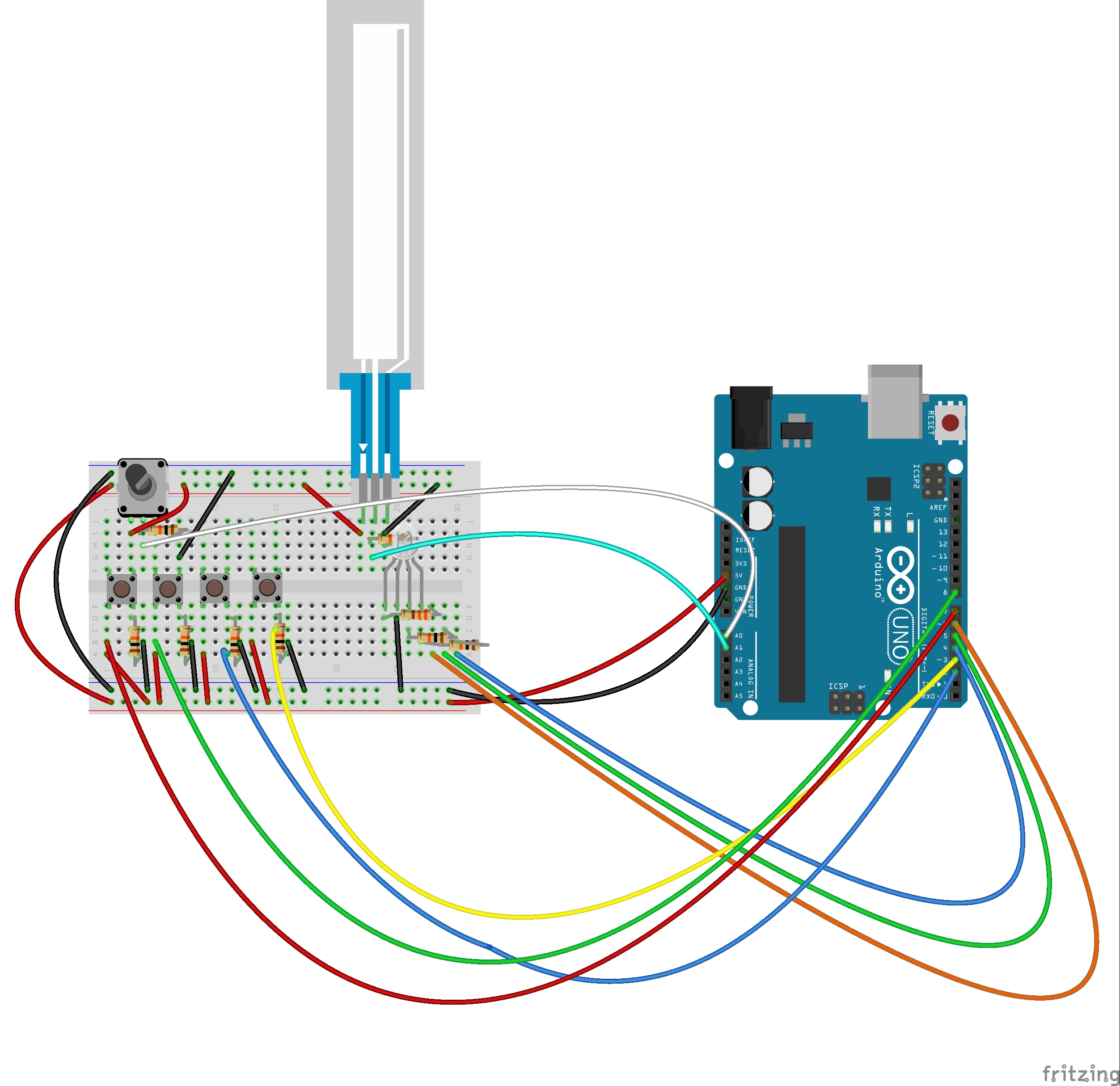
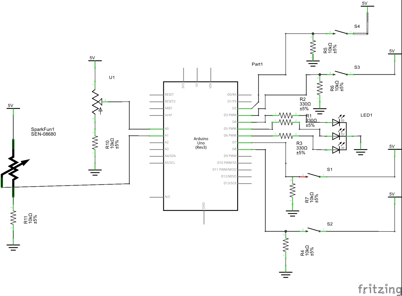
For each of the potentiometers you want to run 5 volts into the right pin, from the middle pin you want to run a wire to one of the analog input pins, in my case I used A0 for the knob potentiometer and A1 for the soft pot. You also want a 10K Ohm resistor running to ground from the middle pin. Then you want to run a wire from the left most pin into ground. For the buttons you want to run 5 volts into one end and then out of the other end you want to run a 10K Ohm resistor to ground and a wire to any digital pin, I used 7, 8, 3, and 2. Then for your RGB LED you want to run the ground pin to ground and use a 330 resistor to direct the current to the wires which connect to other digital pins, I used 4, 5, and 6.
The Arduino code used can be viewed below.
The comments in the code should explain the majority of what the code does, but basically it monitors the state of all the devices and calls a function when appropriate. For example, when the state of the red button changes it calls the colorRed() function which can be seen below.
[cpp]
void colorRed() { //turns the LED and the color of drawing red
digitalWrite(LEDblue, LOW);
digitalWrite(LEDgreen, LOW);
digitalWrite(LEDred, HIGH);
Serial.write(‘c’);
Serial.write(255);
Serial.write(0);
Serial.write(0);
}
[/cpp]
Similarly when the soft pot reads a value between two numbers it will call a function to move the line appropriately, such as movedown() seen below
[cpp]
void movedown() { //moves the line down
Serial.write(‘d’);
Serial.write(xVal);
yVal = yVal += 1;
Serial.write (yVal);
delay(100);
}
[/cpp]
I set up the code calling so many functions so the loop() function can be rather simple and simply call a function when it is needed.
I could not upload the Processing code that was used, but it was provided by my instructor. I made one small change to the code, I changed the point so that the lines draw to the sides, and not to the middle. I did this by changing prevX from width/2; to width; and did the same to prevY and height.
The project could use a few improvements. As state earlier changing to colors that are mixes, such as magenta, yellow, and cyan, are very difficult to work properly. In addition we do not have access to the colors white or black. I almost coded these in, but given the difficulty of getting the colors when pushing only two buttons, I doubt it would be able to press and release three at the same time. One way to fix this would be to move the project to a bigger breadboard and add more buttons. I only had four to work with and it was too late to gather more by the time I realized my initial play, which is what I used, was not the most effective. The knob potentiometer is also a little rough on the hand to use after a while, I tried to correct this by using a pen to make a make shift knob. However, this does not stay put all the time and it sometimes moves without moving the knob pot, causing occasional glitches while drawing. And on rare occasions the soft pot will say it is receiving input when no one is touching it. This could just be the hardware, but it could also be a small glitch in the code or wiring and could possible be corrected. There is also a bit of a delay caused when one switches colors it makes it so we have to wait a few seconds for the device to begin drawing again. I believe this is just caused by the Processing code working through each command and byte, but if it could be corrected it would be a nice way to clean it up.
Thank you for reading!